| Sign In | Join Free | My xxjcy.com |
|
| Sign In | Join Free | My xxjcy.com |
|
| Categories | Light Testing Equipment |
|---|---|
| Brand Name: | Kingpo |
| Model Number: | KP-9709 |
| Certification: | Calibration Certificate |
| Place of Origin: | China |
| MOQ: | 1 |
| Price: | To be quoted |
| Payment Terms: | T/T |
| Supply Ability: | 50 set/ month |
| Delivery Time: | 30 working days |
| Packaging Details: | safety carton pack or plywood box |
| Power: | 220V 50/60Hz |
| standard: | IEC 61347-1 |
| PSU1 voltage: | 10~500V |
| PSU1 current: | max 3A |
| Company Info. |
| KingPo Technology Development Limited |
| Verified Supplier |
| View Contact Details |
| Product List |
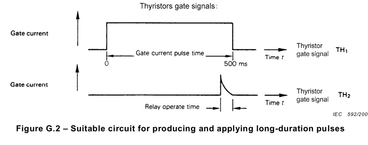
IEC61347-1-Figure G.2 – Suitable circuit for producing and applying long-duration pulses
Technical parameters:
1. Test times: 1 ~ 9999 times
2. Pulse width: 0.01 ~ 9.99 seconds
Interval: 1 ~ 99 seconds
3. PSU1 pulse voltage peak adjustable range: 10 ~ 500V
The maximum output current of PSU1 pulse power supply is 3A, and
the load load adjustment rate shall not exceed 2%
4, R: 100 Ω, C:0.1 uF
5. The power supply of PSU2 product is additionally configured by
the user, and the user inputs it at the terminal of the back panel
of the instrument
6. Output pulse is controlled by high voltage and fast power
device, and the starting time is about 1uS
High backpressure fast reverse bypass diode, recovery time does not
exceed 500nS
7. Pulse observation: test the external oscilloscope by the user
8. Power supply: AC 220V/50Hz;
9. Working environment: temperature: 0 ~ 40℃; Relative humidity
≤90% and no condensation
10. Equipment size: w600mm * d600mm * h500mm, weight about 60kg

Components
PSU 1 power supply unit, capable of supplying maximum pulse voltage
required (maximum of voltage range + X design voltage) with pulse
current demanded by invertor at this voltage with 2 % regulation
(no load to full load).
PSU 2 power supply unit adjusted to maximum of input voltage range.
NOTE 1 Preferably both PSUs should be fitted with current limits to
prevent damage in the event of the invertor under test breaking
down.
TH 1 main switching thyristor used to apply voltage pulse to the
invertor. Many common thyristors should be suitable for this job.
They shall have a turn-on time of about 1 ms and adequate pulse
current capability.
TH 2 thyristor controlling the action of the relay RLC.
D 1 reverse current by-pass diode for TH 1 . Allows initial
oscillatory transients to operate. Shall be fast type (200 ns to
500 ns) with voltage rating equal to twice the maximum pulse
voltage.
D 2 blocking diode for PSU 2 . Prevents output impedance of PSU 2 ,
loading voltage pulse source (PSU 1 ). Shall be fast type
(approximately 1 ms turn off) with voltage rating equal to twice
the maximum pulse voltage.
RLC pulse termination relay with contacts K.
R and C spark suppression components.
Suggested values are 1 00 W and 0,1 mF (for 26 V invertors).
S 1 switch used as ON/OFF or reset control.
NOTE 2 The delay system for securing the correct duration of the
pulse is not represented on the figure. It shall ensure the
triggering of thyristor TH 2 500 ms after the action of TH 1 ,
account being taken of the operating time of the relay.

|
